|
Tutorial - VC-Z HALCON Image Acquisition Interface
1.0
|
|
Tutorial - VC-Z HALCON Image Acquisition Interface
1.0
|
We have a first skeleton script to open the test images. Now we have to implement the image processing task. Reminder, the application is described below.
The camera will see a Box with a circle pattern on the upper face. The aim of the application is to detect the 3D position of the Box.

To achieve this image processing topic, we propose this method:
This step is done simply by the operator:
The result 'Edges' looks like this image:
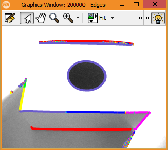
We have to filter the 'Edges' results in order to keep the biggest elliptic one.
At first we can remove very small edges by filtering with a 'length' > 50 px and concatenate adjacent result edges:
The result 'UnionContours' looks like this image:

Then we can filter them with the 'compactness' feature in order to keep the most rounded shapes.
Finally we keep the longest one:
The result 'CircularPattern' looks like this image:
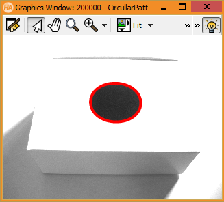
At this step we keep only one edge in 'CircularPattern' that must be the circular pattern. To compute the 3D Pose from the circular shape, we can simply call the operator 'get_circle_pose()':
The operator 'get_circle_pose()' need a calibrated camera, we have to compute the internal camera parameters 'CamParam'. In this simple sample, we use theoretical internal camera parameters. So the 3D position will be computed but it will not be accurate like we are using a real CamParam.
In our sample the circular pattern on the box has a diameter of 5 cm. So we specify a radius of 0.025 meter.
We can see there are 2 3D Poses in output. It is due to a ambiguity on the orientation of the circular shape seen as an ellipse.
The first three elements of the output parameters Pose1 and Pose2 contain the position X, Y and Z in meter of the center of the circle. The following three elements contain the 2 possible orientations due to the elliptic ambiguity. The 6th value for the rotation around the z axis is set to zero, because it cannot be determined.
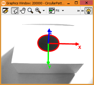
We can show the 3D Pose simply by the call of this procedure:
It draws the 3 axes XYZ on the top of the Box centered on the circular pattern. And the axes will look like a length of 7 cm.
The result looks like this image:
At the end we will display the teapot under the box. We have to read the CAD file at the beggining of the sript:
For each 3D pose detected, we can project the CAD file on the 2D image:
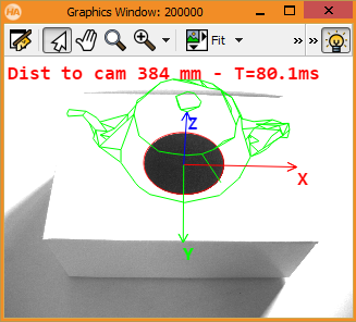
You can get the complete source code here and the teapot CAD file.
Next section: How to run the Vision Application inside the Camera