|
VCLib Documentation
6.12.2
|
|
VCLib Documentation
6.12.2
|
Color Representation based on Run Length encoded Images. More...
The Color Label Code is an extension and part of the Run Length Code. The color interpretation of the RLC value (0xFFFF as white and 0 as black) becomes senseless. The CLC contains the color instead, the RLC is only used as switching signal. A header at the beginning of the CLC can store several things:
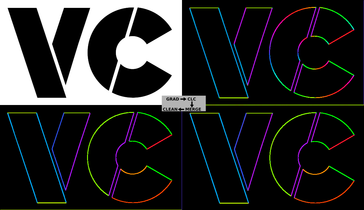
An example usage is the input of a vector image from the gradient_3x3_thresh() function, using the magnitude (st) as guide input and the direction (ccmp1) as color. The threshold selects the strong enough edges, and their direction is stored as color at the CLC. Regions with magnitudes lower than the threshold get the background color at the CLC.
It is important to understand that there is an exact correspondence between Run Length Code entries and color stored in CLC. The byte count of RLC and CLC are identical. This is depicted at the following table. For a better understanding, the RLC and CLC data is displayed side by side.
| RLC Meaning | RLC Address (U16*) | CLC Address (U16*) | CLC Value/Meaning |
|---|---|---|---|
| SLC LSB | 0 + pRLC | pCLC + 0 | RLC LSB |
| SLC MSB | 1 + pRLC | pCLC + 1 | RLC MSB |
| dx | 2 + pRLC | pCLC + 2 | Maximum Color for Circular Arithmetic, e.g. 128 or 256. |
| dy | 3 + pRLC | pCLC + 3 | Designated Color used as Background Color Number. |
| Line Start Xolor | 0 + 4 + pRLC | pCLC + 4 + 0 | Color of corresponding RLC Line Segment. |
| Xolor Toggle | 1 + 4 + pRLC | pCLC + 4 + 1 | Color of corresponding RLC Line Segment. |
| ... | ... | ... | ... |
| Xolor Toggle | n - 1 + 4 + pRLC | pCLC + 4 + n - 1 | Color of corresponding RLC Line Segment. |
dx: End of Line | n + 4 + pRLC | pCLC + 4 + n | -to be ignored- |
| Line Start Xolor | n + 1 + 4 + pRLC | pCLC + 4 + n + 1 | Color of corresponding RLC Line Segment. |
| ... | ... | ... | ... |